
You have found www.hamrx8.com
Copyright.... Website created & maintained by GHQP

 |
 |
_result.jpg) |
 |
 |
_result.jpg) |
 |
 |
 |
 |
 |
 |
 |
 |
 |
 |
 |
 |
 |
 |
 |
 |
 |
 |
 |
 |
 |
 |
 |
 |
 |
 |
 |
_result.jpg) |
 |
 |
 |
 |
 |
 |
I have come up with a way that not only holds the linear rails into the existing Predator Rail extrusions very securely with zero modification but means that you only need a linear rail maximum length of 800mm (You could also get away with minimum 700mm length). Fundamentally I have simply replaced the 3D printed carriers with sections of a standard available aluminium U-Channel extrusion (40mmW x 20mmH x3mm Wall). I chose to use my CNC Router to machine this aluminium extrusion but it could also be done with drilling round holes and threading M3 to hold the linear rails in place. This U-Chanel/Linear Rail assembly is then slid into the existing Predator rails and secured with M3 T-Nuts.
A bit of background. When I first conceived this idea and implemented it I used two 400mm sections of aluminium U-Channel two for each leg butted together. I purchased 1M Linear Rails that I subsequently cut to 850mm just to be cautious in case I found I needed it (I did not). I machined these 400mm sections with slots at the bottom that could accomodate standard M3 nuts and 3mm slots spaced along the sides for securing the U-Channel into the existing Predator extruded rail slots using M3 T-Nuts. This first set of linear rails were low cost Chinese clones that were not that good and presented me with a few challenges getting the to slide smoothly. However after learning how to rebuild and clean the bearing blocks I did get them to perform really well.
Along with this having a CNC Router I took the existing design for the other parts needed, published by Nadeon on Thingiverse, redrew these with modifications and CNC machined them out of aluminium, finally anodised them. This led to installing the completed linear rail assemblies into my Predator. That was a relatively straight forward process, I also took the opportunity to swap out the original timing belts with a much higher quality version. In the mean time while experiencing the problems getting the clone rails to operate smoothly I had ordered at a much higher cost genuine HIWIN brand rails, should have done that in the first place.
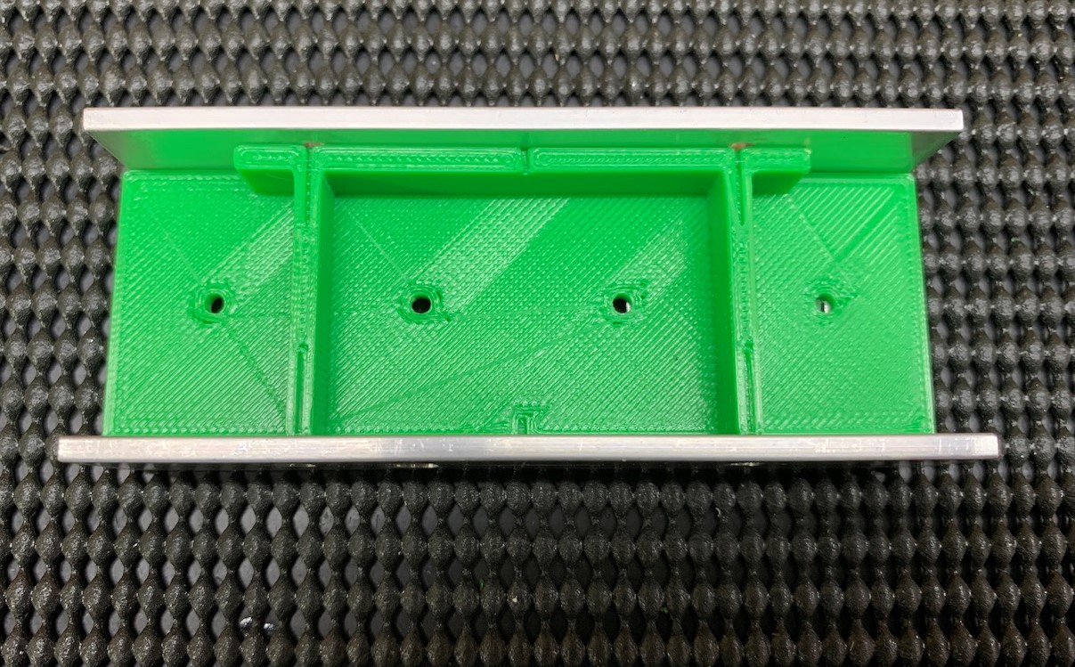
When the HIWIN rails arrived even though I really didnt need to, as the clones proved to be working quite well now, I did swap out the clones for the genuine HIWIN. Now I have a spare set of linear rails. So thinking back of how I had used literally a continuous full length of aluminium 40x20 U-Extrusion to mount the linear rails I realised that I did not actually need to do that where in fact I could have more easily just used 3 to 4 seperate 100mm length sections. So as an experiment I have now made a set and attached them to my spare clone rails.
At the same time I have done some re-designing of the spacers and Carriage (Patin). The CAD/CAM program I use for CNC Routing (Vectric Aspire) enabled me model these and export them as .stl files. That way anyone without a CNC can also print these parts. The new design I came up with for the Carriage is very similar to some I have since seen available on Thingiverse and even though I have not downloaded these designers .stl files to check, I believe they would fit equally as well as my design as a substitute. The modeling of files for .stl export by Aspire is not as good as it could be, its not a program really designed for that purpose but it does work pretty well.
Now to my U-Chanel Extrusion as I mentioned above it is a standard profile 40mm Wide x 20mm Heigh with a wall thickness of 3mm.
I have included in the downloads section at the bottom of this page a dimensioned .eps and .pdf drawing showing both the machined slots and drilling hole locations.
Also you will see on this page a set of photographs showing a lot of detail with some containing notes and other relevant information. These photographs are available for download.
Then there is a download of all the .stl files. Plus a seperate download of dimensioned .eps drawings for all these parts.
Included also are the original Vectric Aspire files for download, just in case anyone has Aspire and a CNC.
I have also now included a set of .stl file to print Drilling Alignment Jigs for the Aluminium U-Channel sections.
The final update to this page was to add a download and instructions on Re-Calibrating the Predators Arm length after the Linear Rail Installation.
This website also has a Contact Me form if anyone has any questions.

Please note that all the information and downloads provided on this page are intended for personal use only.
If you intend to use any of this information for commercial purposes please contact me for authority before doing so.
If you intend to use any of this information for commercial purposes please contact me for authority before doing so.
Page Created September 2020
DOWNLOADS
Set of still images (same as above) some have comments and text information:
.stl files for for the parts that are 3D printed:
.eps and .pdf files of parts including dimensions:
Vectric Aspire CAD/CAM file of the U-Channel extrusion.

My LINEAR RAIL UPGRADE

Updated: Sept 23 (Error's with .stl files have been fixed)
Screw types and U-Channel Extrusion images with dimensions:


INTRODUCTION VIDEO
CREDITS:
To Nadeon for his concept that gave me the basic ideas to create my own way to install Linear Rails on my Predator.
Though I have not used any of his files directly most of what I have done is formulated from his Linear Rail modification guide.
The main difference is that I have used Aluminium Extruded U-Channel to mount the rails into the existing Predator Rails.
Link to Nadeon's version: https://www.thingiverse.com/thing:4116804

Click the image to play the YouTube Video
Click the YouTube Logo to go to my Channel
Click the YouTube Logo to go to my Channel
There have been various published methods and ways other people have devised to do this and basically all of them take a similar approach beyond the actual securing of the Linear Rails into the existing Predator Rail extrusions.
The two fundamental methods are:
First is to use 3D printed Linear Rail carriers and the second is to directly drill and thread holes into the existing rails for securing the Linear Rails.
My personal opinion is that both these methods have some advantages but also disadvantages.
The first being the use of 3D printed carriers. I dont see this as a very secure way plus you need 1M long linear rails so that the ends can be more securely held down. That is an additional cost.
The other method of drilling into the existing Predator Rail extrusions has it benefits but myself personally, like some others, might not want to do it that way, effecting the external clean look.
First Original Full Length U-Channel Installation

Photo Library - Downloadable as a .zip file.
LINKS
I dont have links for most of materials as such as the screws, fastners and the aluminium U-Channel extrusion as I purchased these directly from local suppliers.
The Linear Rails and Gates GT2 Timing Belts purchased on-line from AlyExpress.
HIWIN MGN12 800mm linear guide rail with MGN12H slide blocks stainless steel MGN 12mm
800mm Maximum length but 700mm would be ok.
Allow 2M per Rail (I Orderd 8M to give me a spare length)
U-Channel Drilling Alignment Jigs .stl Files:
FIXED
*
* UPDATED Sep 20th 2020
*
*
*
Update Note:
Sept 20th reflect a slight modification the the side hole locations used for the M3 T-Nuts in the U-Channel.
There is also an additional set of .stl files. These are Jigs to make accurate drilling of the U-Channel holes.
I recommend if you have previously downloaded any files that have been updated you download them again.
Nozzle Diameter 0.40mm
Extrusion Width 0.40mm
Layer Height 0.20mm
Top and Bottom Solid Layers 3
Outline Perimeter Shells 3
Interior Fill 45 deg Rectangular 25%
Extrusion Width 0.40mm
Layer Height 0.20mm
Top and Bottom Solid Layers 3
Outline Perimeter Shells 3
Interior Fill 45 deg Rectangular 25%
Sugested Printer Settings for .stl filse (may need adjusting to suit the individual item requirments):
U-Channel Drilling Jig's VideoExplanation
Click image to Play
Calibrating the Predators Arm length after Linear Rail Installation:
FIXED
Calibrating the Predators Arm length after Linear Rail Installation.
Once the Linear rails have been installed and all the normal bed levelling has been performed it is necessary to re-calibrate the Delta Arm length to compensate for the fact that the arms have now moved slightly forward from original due to the spacers. Below under Downloads I have included a set of files with instructions on how to do this.
Once the Linear rails have been installed and all the normal bed levelling has been performed it is necessary to re-calibrate the Delta Arm length to compensate for the fact that the arms have now moved slightly forward from original due to the spacers. Below under Downloads I have included a set of files with instructions on how to do this.